CW Testing- Continuous Wave Testing

CW testing is Continuous Wave Testing.

CW testing is the First Phase of Telecom/Mobile Network/Radio Frequency (RF) Planning.

Network Planning/ RF Planning is always start with Continuous Wave Testing Method for all GREENFIELD project.

The main aim of doing CW testing is to gather information to design a propagation model of transmitted signal for mobile communication.

It is carried out to gather actual propagation of mobile signals in different terrain and clutter.

Basic of doing this test is to measure or to know the actual distance, a transmitted signal would travel from a Mobile Base Station that we simply say MOBILE TOWER or SITE.

Propagation Model primarily depends on geography and terrain of a circle.

Secondly it also depends on clutter type e.g. Dense Urban (High rise congested buildings), Urban or Rural area.

This is the traditional method and best method for Model Tuning/Model designing.

This is applicable for all technologies that may be 2G, 3G, LTE or 5G. It is mainly Spectrum dependent test.

With the help of CW testing and Model tuning we can design a model for our network to generate coverage prediction and network planning.

Quality of any network depends on the accuracy of the Propagation Model designed based on CW testing and Model Tuning.

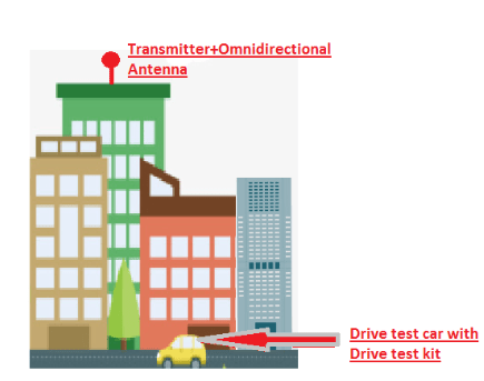
Basic concept of CW testing is very simple-

  1. It has one transmitter along with Omnidirectional antenna which will transmit frequency of corresponding licensed frequency (e.g. 1800Mhz, 900MHz band)
  2. A receiver (Drive test kit) will move around the transmitter and checked for signal strength. How far the Receiver can receive signal from the static transmitter.

Set up of CW Testing:

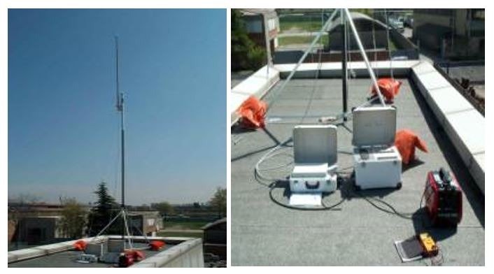
The CW testing equipment contains-

  1. Transmitter
  2. Omnidirectional Antenna.
  3. Power supply to provide power to the transmitter.
  4. Drive test Kit as a receiver.

Now there are two Scenarios for CW Testing.

Scenario-1:

Suppose in a telecom circle or LSA (usually a state e.g. Assam Circle, Maharashtra Circle) there is no Operator is having a new technology (e.g. 4G-LTE or 5G)

When we are planning to start this new technology (e.g. 4G-LTE or 5G) or new frequency band (e.g. 2300MHz, 2100MHz band) in that telecom circle we first have to

Start with Continuous Wave Testing (CW) method.

Then we will use the above mentioned equipment for doing the CW testing.

In transmitter we can set our required frequency to radiate (e.g. 2300MHz band).

Scenario-2:

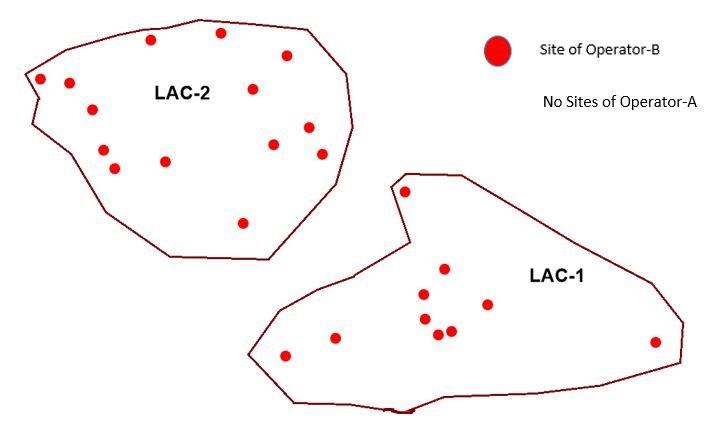
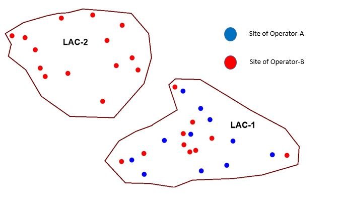
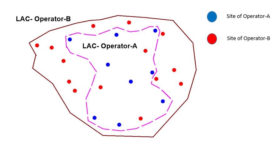
Suppose in a Telecom Circle Operator-A is already giving service of 4G in 2300MHz band.

Operator-B is a newcomer and planning to start 4G network in same frequency band 2300MHz in that same circle.

In this case we do not require to set up the transmitter for radiating the licensed frequency band.

Instead we can use a SIM of Operator-A and do the drive test to check actual coverage level.

In that case we do not require the CW testing set up as the existing operator’s SITE (BTS/nodeB/eNodeB) will do the actual transmission of signals.

Drive test will be carried out by using existing operator’s SIM card.

But if Operator-A is providing services in 2300MHz band and Operator-B is going to operate 4G in 2500MHz band then this method will not work.

We can use SIM card method only for same frequency band.

For different frequency band we must go for normal Continuous Wave testing method with Transmitter+Omnidirectional antenna.

Data Collection by Drive test Method:

The transmitter should place in such a location that it is at the top of a high rise building or some high rise locations from where Omni-directional antenna can radiate to a maximum distance.

Drive test need to carry out in different clutter e.g. Dense Urban, Urban and rural area.

Propagation of signal will be different in different clutter based on penetration losses.

Collection of Samples and Plotting:

In CW testing we would collect samples with the help of drive test kit.

Collected samples can be easily imported in MapInfo Tool. For Final Model Tuning we will use Atoll Planning Tool.

For initial check of collected samples and to analyse the signal quality it is better to use MapInfo as it is fast and simple to operate.

We will discuss about MapInfo tool separately. You can visit my youtube videos to know basic of MapInfo functionality.

https://www.youtube.com/user/hazarikap  (Pranabjyoti Hazarika)

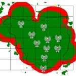
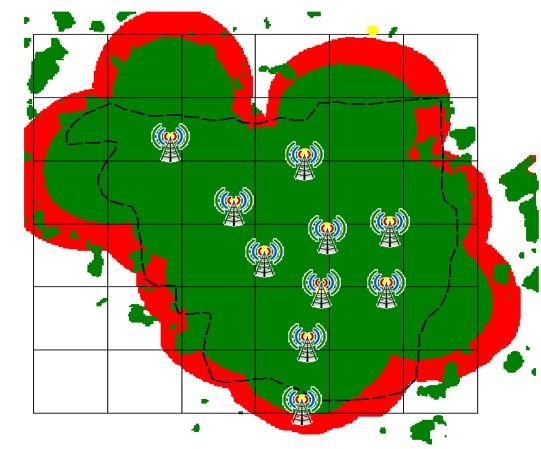
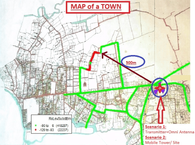
In the above picture it is showing that Transmitter is placed in a fixed position and transmitted a frequency band say 2100MHz (Suppose 5MHz frequency range in 2100MHz band)

The Drive test car with kit were roaming in the town on the motor-able roads.

We have bifurcated all the collected samples in two different parts.

  1. Good Quality received signal : received level from 0 to -93 dBm (Color GREEN)
  2. Poor Quality received signal : received level from -93 to -120 dBms (Color RED)

Now we can see that till 500m distance we are getting GOOD signal level (Color GREEN) in that particular area of a Town.

Beyond 500m distance in some areas we got POOR signal (Color RED).

If we consider this part of the town as URBAN, then we can come to a conclusion that for URBAN area we will consider coverage of a site till 500m distance in 2100MHz band.

If we do 4, 5 sample test in 4, 5 different URBAN areas of different towns then accuracy of the conclusion of coverage prediction will be improved.

But still with 1 sample test also we can conclude to a good value.

Clutter wise sample collection:

So we have completed CW testing and sample collection in 1 clutter, i.e. URBAN

Now we will identify a location of the same town or in different town with high rise congested building area as DENSE URBAN.

In DENSE URBAN we may get a GOOD signal level travelling to a distance of 300m instead of 500m.

In RURAL area this distance may increase upto 1.5Km, 2Km or may be upto 4Km depending on the band of Frequency.

More Frequency band less travelling distance because of more losses in high frequency.

E.g. 900MHz band signal may travel upto 4Km in rural area, whereas 1800MHz band can travel upto 2 to 2.5 Km.

So now we are having collected data/ samples for all 3 category of clutter i.e. DENSE URBAN, URBAN and RURAL.

We also come to a conclusion that with suppose 2100 MHz band we are getting GOOD signal strength

For DENSE URBAN-300m

URBAN-500m

RURAL-1.5 Km

Drawback of CW Testing:

Drawbacks of CW testing are

  1. CW testing model tuning is based on outdoor coverage only. We don’t collect samples inside a building to measure indoor coverage.
  2. Time taking method.
  3. Lot of iterations.
  4. Analogous Transmitter.

Rest it is the best method of sample collections for Model tuning.

In next blog we will discuss about MODEL TUNING which is the 2nd Phase of Network/ Radio Frequency (RF) Planning.

What is MRO in Telecom

MRO-Minimum Roll-out Obligations

The full form of MRO in telecom is Minimum Roll out obligations.

When an operator gets operating licence for a particular frequency band, e.g. 1800 MHz band then that operator has to comply Minimum Roll-out Obligations.

Here operator has to do roll out (site roll out and provide network services) in District Headquarters (DHQ), Block Head Quarters (BHQ), Towns or SDCAs** (Details of SDCA is mentioned in the end of this blog) based on different frequency band.

The test procedures and the roll out phases all are set by Department of Telecommunications (DoT).

The License owner shall make its own arrangements for all infrastructures involved in rolling out of the network and shall be solely responsible for installation, networking and operation of necessary equipment and systems.

MRO compliance is not accepted if done by using technology of network sharing Intra Circle Roaming. 

(This roll out obligation is separated in phases and in each phase no of DHQ, BHQ or towns to be covered is different.

Suppose in a circle there are 33 districts, then to meet 1st phase of MRO-10% DHQ roll out obligation an operator has to complete services in 4 DHQs.

10% of 33 DHQs is 3.3. We can’t do 3, instead we have to complete 4 District Head Quarters.

Any operator which is failed to meet any phase of MRO will attract huge penalty.

In the above picture GREEN colour shows acceptable coverage area for a particular DHQ/BHQ/Town boundary.

Planning, testing procedures and details of reports and other related things of MRO we will discuss separately.

Here let us first discuss what are the phases we have to obey for Minimum Roll-out Obligations and finally about penalty details.

Phases of MRO:

For 700 MHz, 800 MHz, 900 MHz & 1800MHz bands:

  1. For Non Metro Licensed Service Area (LSA or Circle)

Phase 1: Coverage of 10% District Headquarters (DHQ)s/ Towns by the end of first year.

Phase 2: Coverage of 50% DHQs/ Towns by the end of three years.

Phase 3: Coverage of 10% Block Headquarters (BHQ)s by the end of third year.

Phase 4: Coverage of additional 10% BHQs (Cumulative 20% BHQs) by the end of fourth year.

Phase 5: Coverage of additional 10% BHQs (Cumulative 30% BHQs) by the end of fifth year.

For all cases time duration is considered from effective date of license or date of assignment of spectrum whichever is later.

2. For Metro Licensed Service Area (LSA or Circle)

The roll-out obligations for coverage in metro LSAs shall be coverage of 90% of the LSA within one year from the effective date of license or the date of assignment of spectrum, whichever is later.

For above two cases frequency band 900MHz and 1800MHz are treated as same.

For 2100MHz band:

  1. For Non Metro Licensed Service Area (LSA or Circle)

Phase 1: 50% of DHQs in the LSA out of which 15% of DHQs should be in rural SDCA within three (3) years.

Phase 2: Additional 10% of DHQs in the LSA within four (4) years.

Phase 3: Additional 10% of DHQs in the LSA within five (5) years.

For all cases time duration is considered from effective date of license or date of assignment of spectrum whichever is later.

2. For Metro Licensed Service Area (LSA or Circle)

The licensee required to provide required street level coverage using the spectrum in 2100 MHz in at least 90% of the LSA within five (5) years from the effective date of license or date of assignment of spectrum,whichever is later.

For 2300 MHz and 2500 MHz bands:

  1. For Non Metro Licensed Service Area (LSA or Circle)

The licensee of 2300 MHz / 2500 MHz shall ensure that at least 50% of the rural SDCAs are covered within five (5) years of the Effective Date using 2300/ 2500 MHz band of license or date of assignment of spectrum, whichever is later.

2. For Metro Licensed Service Area (LSA or Circle)

The licensee is required to provide street level coverage as prescribed in the test schedule in at least 90% of the LSA within five (5) years of the Effective Date of license or date of assignment of spectrum, whichever is later.

Penalty in MRO:

Any Operator or License owner fails to comply Minimum Roll-out Obligations, it attracts phase wise huge penalty.

The penalty is applicable for each phase separately. If an Operator fails to meet prescribed period of time for two phases, then below mentioned penalties will be applicable twice.

For 700 MHz, 800 MHz, 900 MHz,1800MHz & 2100MHz bands:

  1. @ Rs. 5 Lakhs per week for first 13 weeks.
  2. @ Rs. 10 Lakhs for the next 13 weeks and thereafter
  3. @ Rs. 20 Lakhs for 26 weeks

subject to a maximum amount of Rs. 7.00 Crores for each phase.

For 2300 MHz and 2500 MHz bands:

  1. @ Rs.15 Lakhs per week for first 13 weeks.
  2. @ Rs. 30 Lakhs for the next 13 weeks and thereafter
  3. @ Rs. 60 Lakhs for 26 weeks

subject to a maximum amount of Rs. 21.00 Crores for each phase

For each of the above two cases delay more than 52 weeks in a phase will impose maximum penalty amount and assigned spectrum may also be withdrawn.

**SDCA:

Short Distance Charging Area (SDCA) is a telecom area which is smaller than the size of a district.

DoT (Department of Telecommunications) configures entire telecom network in India in to Telecom Circles (LSA).

Circles are further categorized into Switching Area (SSA) and Long Distance Charging Area (LDCA) which is equivalent to size of a district.

LDCA is further divided into Short Distance Charging Area (SDCA) which is smaller in size than district and Taluka.

## Reference: Notice Inviting Application (NIA);No: 1000/06/2016-WF

Difference between MORAN and ICR

In my earlier two blogs about MORAN (Multi Operator Radio Access Network) and ICR (Intra Circle Roaming) we have discussed about how MORAN and ICR can be used for coverage expansion.

Both technologies are used for sharing of network between two operators.

There is always a seeker and a provider network.

For the seeker operator the ICR or MORAN sites are new sites for their network.

If both technologies can be used for coverage expansion then why we use MORAN in some cases and ICR in some other cases.

There are some major difference we found when we implement these technologies practically.

For theoretical concept you please go through my earlier two blogs of MORAN and ICR-Intra Circle Roaming.

MORAN and MRO:

One major criterion when we use MORAN instead of ICR is Minimum Roll Out Obligation (MRO).

MRO is Minimum Roll out obligation that is set by DoT (Department of Telecommunications).

When an operator gets operating licence for a particular frequency band, e.g. 1800 MHz band there is an obligation set by Government that the Operator has to do roll out (site roll out and provide network services) in District Headquarters (DHQ) and BlockHead Quarters (BHQ).

This roll out obligation is separated in phases and in each phase number of DHQ or BHQ to be covered is different.

E.g. 1st phase of DHQ roll out obligation required 10% coverage of total DHQs.

Suppose in a circle there are 33 districts, then to meet 10% DHQ roll out obligation an operator has to complete services in 4 DHQs.

10% of 33 DHQs is 3.3. We can’t do 3, instead we have to complete 4 District Head Quarters.

Minimum Roll Out Obligation (MRO) itself is a huge topic. I shall discuss this topic separately.

For now we understood that after getting License Telecom Operator has to complete minimum roll out in some areas as per DoT (Department of Telecommunications) guidelines.

In the end final testing for Quality check of  coverage of network of the operator in District Head Quarter (DHQ) or Blok Head Quarter (BHQ) is conducted by TERM Cell (Telecom Enforcement Resource and Monitoring).

During testing TERM Cell representative check the received signal in Drive Test tool.

In drive test tool it shows through which ARFCN (Absolute Radio Frequency Channel Number) we are getting received signal.

ARFNC is directly related to frequency spectrum.

So if we want to complete MRO in a town/ DHQ/BHQ with the help of Network sharing from other Operator we must adopt MORAN (Multi Operator Radio Access Network) instead of ICR (Intra Circle Roaming).

In MORAN only, we use PLMN/ BCCH+TCH of the seeker network. But in ICR we use PLMN/ BCCH+TCH of Provider network only.

So during final testing of MRO it will clearly visible ARFCN/BCCH of the seeker network if we use MORAN.

But in ICR case, testing will be failed as it will show ARFCN/BCCH of provider network only.

This is one major noticeable point in MRO, where we must go for MORAN in lieu of ICR.

There are some basic noticeable differences between MORAN and ICR when we see practical implementation of these technologies.

Some points are tabulated below-

There are lot many differences during configuration and design of MORAN and ICR.

For more details you may please visit my other blogs on MORAN and ICR-Intra Circle Roaming.

So MORAN and ICR both can be used for coverage expansion based on different scenario.

ICR- Intra Circle Roaming

ICR- Intra Circle roaming is sharing of network of one operator with another operator.

The main aim of ICR is to expand coverage in new locations.

There are two types of ICR. Normal ICR and Spider ICR.

ICR can be done on circle basis. E.g. if Operator-A do not have License (2G, 3G or 4G) in a circle (e.g. Assam, Pune or any circle) then Operator-A can provide 3G network

In that particular circle by doing an ICR agreement with Operator-B which is having operating license in that circle.

On site wise basis Operator-A will take ICR service from Operator-B where Operator-A doesn’t have its footprint.

The above 2 cases we consider as Normal ICR.

There is a third scenario where in a same town both Operator-A and Operator-B have coverage.

To improve coverage in the black hole locations we can do ICR in between the two Operators.

Such type of ICR is called Spider ICR

Normal ICR:

Normal ICR has two possibilities-

  1. Network level ICR
  2. Site wise ICR

Network Level ICR:

Telecom circles are divided based on geography. E.g. in India there are 23 telecom circles like Assam, North East,UP East, UP West, Kolkata, West Bengal, Pune, Maharashtra etc.

Telecom operators are like Airtel, Idea, Vodafone, RJio, BSNL, AT&T etc.

In network level ICR, suppose Operator-A doesn’t have license of a particular network service, e.g. 3G in all circles or in some circles.

If one telecom Operator-A doesn’t have license in all circles or in 2, 3 circles then they can take ICR from another Operator-B which is having 3G License in all circles or in those particular circles where Operator-A doesn’t have License.

This type of ICR is easy to implement.

We don’t need to do any new configuration for such kind of ICR.

Operator-B has to open all the LACs (Location area code) of all 3G sites (or 2G or 4G sites) for Operator-A. Then any customer of Operator-A moves to an area where Operator-B has 3G coverage, that customer will automatically latch to the network of Operator-B and will get full 3G services.

Even he will not feel any kind of difference from service point of view.

Sometimes he may require to latch to the network manually or by restarting the mobile if visits to a new circle.E.g. one customer visits from Kolkata to Pune.

In this scenario both LAC-1 and LAC-2 of Operator-B can be open to Operator-A.

Site wise ICR:

In site wise ICR, network service is shared in some locations where one operator doesn’t have coverage and one is having existing coverage.

If Operator-A doesn’t have coverage in a particular location and Operator-B is having existing network, then Operator-A can take ICR from Operator-B in that particular locations.

In this case Operator-B may need to redefine its LAC based on requirement of sites.

In this case we can open LAC-2 of Operator-B to Operator-A to provide ICR service to the customers of Operator-A. All sites under LAC-2 will provide ICR services.

In the above picture we have seen that Operator-A doesn’t have any sites nearby the LAC-2. So we can offer sites under LAC-2 for ICR purpose.

In some cases we may recreate new LACs based on requirement of sites from the seeker operator (Operator-A in this case).

Spider ICR:

Suppose in a town Operator-A and Operator-B both have their own sites and having coverage.

In some points or locations inside the town there is possibility that in some locations Operator-A is having good coverage but Operator-B doesn’t and vice versa.

In that case both operator can come into an ICR agreement which is called Spider ICR.

Operator-A and Operator-B both will access network of each other and will have a good coverage without any coverage hole if combined spreading of coverage of the two Operators is good.

If a subscriber of Operator-A is roaming inside that town he will latch to the site either of Operator-A or Operator-B based on received signal strength.

Whose signal strength is better based on that subscriber will latch to the sites of that Operator.

This method is very much successful in case of 2G.

But for 4G, practically it shows many difficulties, which finally leads to low data consumption in comparison to No-ICR situation. When 4G Spider ICR reverts to NO-ICR zone, data consumption again takes up its pace as it was earlier.

There is no issue with 2G spider ICR and it works very fine.

In this case LAC-Operator-A is open for Operator-B and LAC-Operator-B is open for Operator A.

A subscriber can access network of both operators continuously without any interruption.

LAC – TAC Mapping:

2G-3G LAC Mapping:

In case of 2G or 3G we only require mapping of LAC. LAC mapping is simple. If a seeker operator is asking for some sites from provider operator and those sites are falling

In some existing LACs and they asked for all the sites of that LAC then the process become very simple and we just have to open those LACs for seeker operator.

Suppose an existing LAC has 50 sites,seeker operator asked for all 50 sites then provider operator just need to open the LAC for the seeker.

If seeker operator is asking for 30 sites for ICR then we have to create new LAC for those 30 sites and remaining 20 sites will have separate LAC. The new LAC created for 30 sites will make open for the seeker operator.

Before creating new LAC we have to properly check whether the LAC formation can be properly done or not and it should not impact badly on PSR (Paging Success Rate) KPI.

Moreover during LAC creation we should take care of highway or major roads. So that due to wrong creation of LAC customers should not go into ping-pong effect, i.e. jumps between 2 LACs continuously which is a wastage of network resource.

4G TAC and 3G/2G LAC Mapping:

In 4G we have to create TAC (Tracking area code) boundary to provide 4G ICR to a seeker operator.

TAC corresponds to the Routing Area (RA) used in Wideband Code division Multiple Access (WCDMA) and GSM/ Edge Radio Access network (GERAN).

TA (Tracking Area) consists of a cluster of RBSs having the same Tracking Area Code (TAC). The TA provides a way to track UE location in idle mode.

If seeker operator is asking for 4G ICR then it should have 3G or 2G network within that area for CS fall back(Circuit switch fall back).

It means during 4G connection it is purely packet switched (only data). So to generate or receive call (circuit switch) it requires CS environment.

If 4G network is having VoLTE (Voice over LTE) services and the subscriber is having VoLTE enable handset then till the time he is in 4G coverage area he can talk in 4G network only.

No need to jump to 3G or 4G network until and unless he is out of 4G coverage area and enters into 3G/2G network area where the operator doesn’t have 4G services.

For CS fall back we require TAC- LAC mapping.

TAC-LAC Mapping Principle

  • One or multiple TACs can be part of one LAC
  • Multiple LACs can’t be part of one TAC

Now we can take 2 practical scenarios.

Scenario 1:

Provider Network:  Provider networks operates on 2G, 3G and 4G

Seeker Network:Operates only on 2G. Seeking ICR for both 3G and 4G.

In this case TAC of 4G of provider,first have to mapped to LAC of 3G of provider and finally to LAC of 2G of seeker network.

Then CS fall back will first happen to 3G network from 4G network and if 3G is also not available then finally to 2G network of the seeker.

These settings/mapping have to done site wise.

If in one site provider does not have 3G network then mapping should be such that CS fall back will directly happen to 2G instead of 3G.

Any subscriber’s mobile will not search for 3G if it latch to such site. It will directly search for 2G network from 4G network.

If 4G site is VoLTE enable and subscriber is also having VoLTE enabled handset then no need of CS fall back.It will operate on 4G network only.

Scenario 2:

Provider Network:  Provider networks operates on 2G, 3G and 4G

Seeker Network: Doesn’t have any network. Seeking ICR for 2G, 3G and 4G.

If seeker Operator neither have 4G nor 2G/3G network in a particular location then it requires both 4G as well as 3G/2GICR from provider network.

In this scenario only 4G ICR can’t suffice all requirements.

In this case if we do the mapping as like showing in the below mentioned diagram, i.e. 2 4G LACs mapped to 1 3G LAC and then that  3G LAC mapped to 2, 2G LACs then TAC-LAC-Mapping-Set-1 will supersedes                        TAC-LAC-Mapping-Set-2 and 2nd set of mapping will not work.

So for that either we have to separate one 3G LAC to 2 separate LACs or the 2 LACs of 2G need to combined to 1 2G LAC.

Both arrangement will work properly.

Revenue of Provider from the Seeker operator:

How provider operator would get revenue from the seeker operator it’s totally depends on the agreements between the two operators.

There may be 1, 2 cases.

  1. Site to site basis– here seeker operators has to provide a minimum amount per site per month e.g. 12K per site until some threshold traffic level. 

After crossing the threshold level of the allowed traffic cost will be calculated based on traffic usage in addition to the monthly charges.

If traffic of the seeker network goes high revenue of the provider network also goes high.

  • Take and Give-here both operators come to an agreement that both will provide ICR to each other same no of sites in different locations depending on which operator is dominant in which location. In this case no monetary benefit to anyone from each other, but coverage footprint will increase for both operators.

So through ICR agreement an operator can expand its coverage footprint in new areas without any involvement of CAPEX.

MORAN

Multi Operator Radio Access Network

MORAN-Multi Operator Radio Access Network, the name implies the sharing of RAN of two operators. MORAN is mainly used for coverage expansion with less hardware cost.

RAN sharing was standardized from Rel.6.

In two scenarios we can go for MORAN.

  1.  2 Operators are having their own networks in an area.
  2.  Only single operator present in an area. 2nd Operator does not have   their presence.

In both scenarios finally expansion of footprint is the main aim for implementing MORAN.

Scenario-1:

If 2 operators are having their presence in an area, there may be some locations where two operators will have coverage overlap and some locations two operators will have exclusive coverage. So to maximize the coverage area we can select the exclusive coverage sites for MORAN implementation.

If Operator-B is taking a site form Operator-A through MORAN that site will be like a new site for Operator-B.

Scenario-2:

If only one operator is present and 2nd operator does not have coverage then this is totally a new coverage for the seeker operator.

How MORAN works:

In Moran both networks will use same radio equipment, same transmission equipment and bandwidth till the MSC of host network. A connection is established between MSC to MSC of both networks which is called NNI – Network Network Inter-connectivity.

The only thing that we have to define is PLMN of both networks in the same cell. If operating frequency of the 2 operators is same (e.g. both operators are having same spectrum 1800MHz band) then we do not need any extra hardware in a cell.Just we have to define PLMN separately and in BSC this option is available.

If both operators are having different frequency spectrum (e.g. one at 1800MHz and1 at 900 MHz band) and the existing equipment (Antenna and radio) does not support both spectrum then we have to add additional antenna and radio baseband unit.

Transmission media will be same in both cases. Just we have to check that host network has enough transmission bandwidth to support the expected traffic of the seeker operator.

If expected total traffic of the seeker and the host site is more than current traffic handling capacity of the host site, then capacity augmentation would be required. For GSM addition of TRX and for 3G and 4G addition of additional bandwidth (e.g. License up gradation from 10MHz to 15Mhz bandwidth).

Implementation of MORAN:

We can take an example how practically MORAN can be implemented. We are taking this example for a single site for GSM MORAN.

  1. Site – A (Host site) and Site-B (Seeker site)
  2. BSC of Site-A is BSC-A, and Site-B is BSC-B.
  3. Core of Site-A is Core-A and Site-B is Core-B.

 If we consider a scenario where both operator operates in different frequency band need additional antenna and radio unit.

Configuration in Host BSC:

  • Some features need to implement in the BSC
  • Multiple PLMN support in BSS
  • Multiple CN support

BSC and Core connectivity:

BSC-A needs to be connected to Core-B (CS/PS) via NNI.

Site-B cells will be visible in Site-A OSS as these cells are part of BSC-A.

Though this process looks very simple, yet so many definitions and configurations required in both host and seeker network.Additional hardware not required, but involvement and configuration required atRF, Transmission and core end. Once for the 1st time a sample site implementation successfully completed then further tasks become simpler.

So through MORAN concept we can reduce effective cost of a BTS site and without new BTS/Base station we can expand our network coverage footprint.

P.S.- You should also read about ICR-Intra Circle Roaming which is another method of Network sharing method but with different concepts and also what are the differences between MORAN and ICR.

https://saiwisdoma.com/icr-intra-circle-roaming/
https://saiwisdoma.com/difference-between-moran-and-icr/

Thank you for reading so far. You are important for me, please leave your footprint here:

[mc4wp_form id=”173″]
<script async src="https://pagead2.googlesyndication.com/pagead/js/adsbygoogle.js?client=ca-pub-2754967439384345"
     crossorigin="anonymous"></script>

5 Building Blocks of 5G-NR Technology

5G is the fifth generation of cellular mobile communications .Demand for mobile data increasing exponentially across the world. Voice on mobile phone is no more a criteria for selection of any network. The whole telecom market is playing on data only. Consumption of data is increasing drastically in a very short span of time.

As data feasting increasing tremendously so up gradation of technology become necessity with the ecosystem. Data was started with 2G, 3G then 4G and finally with 5G. Technology is upgraded to next generation with an expected high data rate capacity.

Speed-

Technology wise expected speed of data in optimum conditions is as below.

2G download data speed – 100Kbps.

3G download data speed – 21.6Mbps.

4G peak download capacity – 1Gbbps (Stationary); 100Mbps (Mobile).

5G peak download capacity – 20Gbps (Stationary); 1Gbps (Mobile).

Along with speed, latency is also one criteria expected from upgraded technology.

4G and 5G are totally based of packet switch network (PS) only.  2G is inherently circuit switch (CS) network. 3G is hybrid of circuit switch (CS) and packet switch (PS) network.

Main objective of 5G performance are high data rate and low latency.

Building blocks of 5G-

We can say 5 Building blocks of 5G are (but not limited to…)-

Frequency Spectrum-

Frequency band for 5G is in millimetre waves with frequency band 26GHz, 28GHz, 38GHz and 60 GHz.

Allocated lower frequency band from 600 MHz to 6 GHz.

Specially it usage the frequency band 3.5 GHz to 4.2 GHz in this lower frequency band. 

3.5GHz frequency is very important as it is likely to be globally harmonized.

However the speeds in lower band is only moderately high from 4G speed.

Antenna System-

In 5G antenna system is Massive MIMO (Multiple Input Multiple Output) technology where it comprises 64-256 antennas.

If we consider 1 physical antenna contains 8 dual polarized antenna elements and 1 sector usage 8 physical antennas then total antenna per sector would be (8*8=64). So 192 antenna elements per site.

For more details on Massive MIMO you should also read about Massive MIMO here.

Cell Site-

As 5G frequency range is in millimetre waves the absorption of signal is very high by buildings, trees, water and other particles in air.

Penetration of signal would be very low. Coverage distance of a cell site would be very less.

To cover a particular location requirement of no of cell sites will increase. In urban area 1 cell site would cover approximately 200m distance.

So regular macro cell sites (coverage range is approximately 500m to 2 Km for 4G) would be replaced by lot of small cell sites.

Beamforming-

In massive MIMO (multiple input multiple output) technique we use large no of antennas. The beamforming of these antennas are very much directive. So it is almost like serving individual user.

It has a very narrow main lobe, like laser-beam. Side lobes are very tiny. Less leakage in undesired directions.

Array gain of antenna is: 10 log10 (MA), where MA= no of antennas.

Transmission Backhaul-

3G, 4G or 5G, any technology can’t provide expected data speed until and unless we have a strong backhaul connectivity. Connectivity from Core (Switch) to BSC/RNS and finally to the base station (nodeB/enodeB) is the backhaul connectivity.

If we have high capacity backhaul till the BTS end then only we can get a high data speed on air interface between base station and our mobile station.

For 4G and 5G, Fibre backhaul connectivity is a major requirement.  Without Fibre connectivity expecting a speed of 1Gbps or 20Gbps is beyond expectation.

Challenges-

Some major technical challenges of implementation of 5G are-

  • Large space requirement for installation of Massive MIMO antennas.
  • Roll out of huge no of small cells.
  • Readiness of strong backhaul connectivity.

There are many other challenges like acquisition of new locations for small cells, etc.

There are many issues in hand but they all are solvable.

1st 5G deployment country-

The 1st country to launch 5G network is Qatar. Ooredoo a large mobile operator commercially launched 5G network in May 2018 in 3.5Ghz band.

Vodafone Qatar has also launched 5G in August 2018 in 3.5 GHz band.

Thank you for reading so far. You are important for me, please leave your footprint here:

[mc4wp_form id=”173″]
<script async src="https://pagead2.googlesyndication.com/pagead/js/adsbygoogle.js?client=ca-pub-2754967439384345"
     crossorigin="anonymous"></script>